Revit MEP
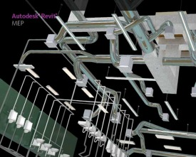
Revit MEP - the BIM solution tool - works the way engineers and designers of Mechanical, Electrical, and Plumbing systems think, with tools to intuitively create, design, and document building systems. Revit MEP helps engineers and designers visualize their designs before they are built, to minimize design coordination errors between the engineering and architecture teams working on integrated projects. With its parametric change technology, any change is automatically coordinated everywhere in the project, including model views, drawing sheets, schedules, sections, and plans. Design and documentation stay coordinated, consistent, and complete. Partner applications and built-in tools for building performance analysis support better design decision making in more cost-effective, environmentally conscious designs and energy - efficient buildings.
Sustainable Design Support
Revit MEP software provides integrated heating and cooling loads analysis tools to help you perform energy analysis, evaluate system loads, and produce heating and cooling load reports for a project. Provide optimal systems design with the same building information model, with realistic, real-time design scenarios aiding better decision-making support. Revit MEP helps to minimize design errors and better define your project’s overall sustainability strategy. Take full advantage of the data-rich Revit MEP model to support better decision making through integrated building performance analysis tools. Revit MEP also supports green building extensible markup language (gbXML), containing information for spaces and zones as well as lighting fixture element data. Export the gbXML file for use with a third-party analysis application for calculating loads. Create high-performance, sustainable buildings with extensive analysis of heating and cooling load, LEED daylighting, thermal energy, and more.
Duct and Pipe Sizing / Pressure Calculation
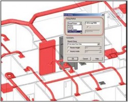
Built-in calculators make it possible to perform sizing and pressure loss calculations according to industry-standard methods and specifications, including the American Society of Heating, Refrigerating, and Air-Conditioning Engineers (ASHRAE) fitting loss database. System sizing tools instantly update the size and design parameters of duct and pipe elements, without the need for file exchanges or third-party applications. Select a dynamic sizing method for the ductwork and piping systems in your plans using Duct Sizing and Pipe Sizing tools. Use the friction, velocity, static regain, or equal friction sizing method for duct sizing. Use the velocity or friction method for pipe sizing.
Duct and Pipe System Modeling
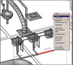
Intuitive layout tools enable easy model modifications. As always, Revit MEP software automatically updates your model views and sheets, helping to maintain document and project consistency. Create HVAC systems with mechanical functionality providing 3D modeling for ductwork and piping. Easily modify the model by dragging design elements on the screen in almost any view. Modeling can also be done in both section and elevation views. All model views and sheets update automatically whenever a change is made anywhere for accurate, coordinated designs and documents at all times.
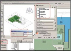
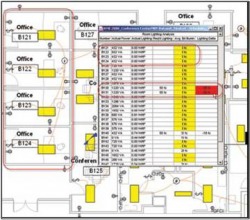
HVAC / Electrical Space Design
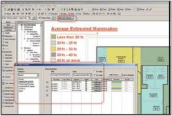
Communicate design intent visually with room color-fill plans that facilitate client validation of design reviews and criteria. All revisions and alterations to color-fill plans are updated automatically across your model. Create any number of schemes, and maintain consistency for the duration of your project. Three-dimensional modeling for ductwork and piping enables you to create HVAC systems that can be clearly shown using customer color schemes for design airflow, actual airflow, mechanical zones, and more. Create electrical color schemes for power loads, lighting per area, and more. With color schemes, deciphering spreadsheets and using colored pencils on printed plans are no longer necessary.
System Inspector
Quickly identify and adjust high pressure loss areas in your system, enhancing economy and efficiency. Interactively modify fittings, shape, or configuration, and instantly see the updated static pressure loss and changes to flow properties. Revit MEP software displays the critical flow path for branches, main trunks, or entire systems.
Parametric Change is Better for Coordination
Revit MEP software helps maximize the effectiveness of leveraging your architectural and engineering BIM design and construction documentation processes. Enhance client communications and accelerate decision making through in-process visualization. Smoothly collaborate with Revit Architecture and Revit Structure using a Revit model. Built on the latest version of the Revit platform, Revit MEP provides all the competitive advantages of BIM.
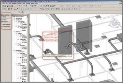
Interference Checking
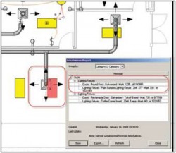
Coordinate major building elements and systems during design, avoiding collisions between elements and reducing the risk of construction cost overruns. Choose which building elements to check for interference, whether duct and structural beams, or lighting fixtures and diffusers. Revit MEP automatically generates a report with the ability to zoom into the area of interference for easy clash resolution.
Bi-Directional Associativity
A change anywhere is a change everywhere. Storing your information in a single, consistent database helps to ensure that your entire model is always up-to-date. Parametric technology automatically manages all change propagation and keeps your project on track. The ability to change a schedule and automatically update the model is a key benefit of using Revit MEP software.
Panel Schedules
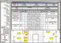
Automatically create electrical panel schedules in your designs. Balance loads or change circuits for a device through panel schedules. Easily edit the panel circuits through a built-in panel circuit editor. Panel schedules can be formatted like most Revit schedules. Benefit from multiple panel schedules and the ability to change electrical devices directly in the panel schedule.
Lighting and Power Circuitry
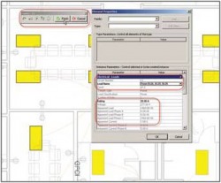
Use circuits to track loads, monitor attached devices, and verify circuit lengths. Define wire types, voltage ranges, distribution systems, and demand factors to prevent overloads and mismatched voltages. Accurately calculate the estimated demand loads on feeders and panels to size equipment quickly and efficiently. Using circuits to track loads, number of devices, and circuit lengths helps to minimize errors in the electrical design. Create high-performance, sustainable buildings with extensive analysis of heating and cooling load, LEED daylighting, thermal energy, and more.
